2018年10月1日 星期一


NoteThere are many ways to DIY a Jubeat Controller, the following below ONLY shows my personal experiences and not the best sample.


First we check the hardware requirement of Jubeat in first generation


CPUIntel Celeron M 1.5GHz

RAMDDR333 1GB

BoardIT855GME-LX (AOpen,Inc.)

DriveSil 3512A SATARaid (Silcon Image,Inc.)

           WDC WD 1600AAJS Size 160GB

OSKONAMI Windows Xp Embedden System Ver 4.10

Sourcehttps://www.ptt.cc/bbs/MusicGame/M.1236961674.A.0D9.html


We found that most computer requirements are higher than that

So only thing we need to solve is launching the game with 16key controller

There are some programs spreading on internet for people building their own game environment


One is Jubeat Analyzer by a talented Jubeat Gamer
Pros
Interfaces & Music Tracks can be customized

ConsHard to use


Second is The HDD

Which means someone crack and clone the official hard drive to make the files

ProsWhat you get is as same as the arcade machine
Cons
This pirated issue is illegal


I was going with another way

I bought the original HDD with a official USB DRM KEY

Launching the game after settings.


To avoid some law problems so I just have these hints

You can get any data you need just Google with the correct words.


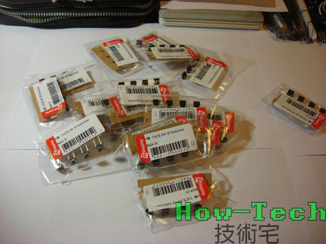
Then we start the part of 16key controller

At first I use Arduino Uno with flashed HEX to emulate HID keyboard & joystick

But I found that the Arduino doesn’t work properly because the problem of Keyboard Ghosting and the Clock Rate on the board


So I changed to Arduino Leonardo in the end.

Just because this board is native supporting HID

Leonardo will be the bridge between computer and buttons
The board sends pressing signal from buttons to computer via USB

How it works:
 

So I made this protype


16 button pair to 16 key on the arcade


After the button test passed, we need to make keys and cases


I use Adobe illustrator to generate SVG for models

Then send the files to a acrylic process studio 


 The keys were bonding 3 layers with choroform


There should be 4 buttons around the key


So this is how I put all together:


 The result:


2016年7月31日 星期日


Sometime I practice my guitar. But I usually tune my guitar by my ear.
Once I want to tune correctly but I found my tuner has broken after I used it.
Maybe i'ts time to get something repaired

My tuner

I found the problem after i opened it up
The buzzer in tuner was cracked
So I just bought another buzzer and try weather will it works or not
While I was doing this I was very carefully, I was afraid that make something else broken.
Then Finish.

The tuner works again after I just changed the buzzer.


Arduino is one of the most common tool in open source. Include me is in study in this projects.
So I am going to teach [How To Build An Arduino Board] by yourself and it's more cheaper.
(There are a lot of open source boards like Raspberry Pi、LinkIt and Newton to choose.)


Start 
The Data Sheet of CPU on board.
(This kind of datasheet can be found in IC company website)


 I made this draft after I read the guide in Arduino web.

And the material for building
Capacitor 104 x1 
22p capacitor x2 
10k resistor x1 (connection with Reset) 
16MHz quartz oscillator x1
  
Finish~ (I did so fast that I forgot to take picture on process...)
This is the adapter mod from TTL to USB

TTL (Transister-Transister-Logic)
Means using 0V-5V as the switch to operate the signal 0 and1.

Few days ago, math teacher from school brought me an old Acer because his computer need restore. (The computer has so many virus)
I found that the virus made the windows crash so seriously after I checked up.

Acer Aspire M3300 (Rate seems good)
Some details about computer
I plug my monitor and some stuff to the computer
Inside

Choose USB - Compact to boot
And I put Windows 7 Ultimate into the USB
Installing
Done !
Finally I just install drivers and some common software.
I return the computer back after all. ( And the teacher looks happy)


2016年1月31日 星期日


Last time I made the part of controller.

This time I are going to build the car circuit.
 (There are some problems about the circuit . Transistors are already included in L293D,so there is no need to add transistors between driver and motor.)


Then soldering the parts…


Finish


 We got the main part of the car after inserted IC

Next step we need set the motor

I use SG90 and turn the servo power by DC directly


I add two 2.2k ohm resistances to the sensor board inside the servo

and shave the latch on gears.


 In the end I put everything together


2015年12月18日 星期五


I played some remote cars in my childhood, sometimes I teared down those cars even and check the look of parts .


Now I watch some videos about building remoting toys via Arduino like tank, helicopter, web cam with car . . .etc

Therefore, I also want to a remote toy on my own!

 
Here is the staff I bought.

Encoders : HT12E/D
Motor Driver : L293D
Wireless Module : SHY-J6122TR
2-DIP Switch with 8 slides
Motor : x2
Button : x4


Here is the circuit


Finish the part of Controller
2017 How-Tech 技術宅 © Planer - Responsive Blogger Magazine Theme - Published By Gooyaabi Templates
Planer theme by Way2themes